
-
An antigravity propulsion mechanism

Page under construction
Page en constructionArticle publié sur notre site avec l’aimable autorisation de Vasileios Th. Tsiriggakis et Christopher G. Provatidis, reproduction interdite.
Article published on our site with courtesy of Vasileios Th. Tsiriggakis and Christopher G. Provatidis, reproduction prohibited.
A new concept and design aspects of an ‘antigravity’ propulsion mechanism based on inertial forces
Μελέτη που υποβλήθηκε από τον κυριος Vasileios Th. Tsiriggakis
- Christopher G. Provatidis
National Technical University of Athens, Zografou Campus, Athens, GR-15780, Greece
Full Professor, Department of Mechanical Engineering, 9 Heroes of Polytechnion Avenue, AIAA Associate Member, ASME member.
and
- Vasileios Th. Tsiriggakis
NTUA external collaborator, Athens, GR-10447, Greece
Control & Telecommunications Engineer, MBA, 2 Naoussis Street.
This paper proposes a breakthrough innovation in the framework of the non-rocket spacelaunches. It is proposed to reduce the use of usual rocket systems through a new inertial propulsive system or/and through a hybrid new antigravity system in conjunction with conventional rockets of low-power or other means.
Nomenclature
a = index referring to the lumped mass ‘a’ b = index referring to the lumped mass ‘b’ Fxi = X component of the inertial force acting on the i-th lumped mass (i = a or b) Fyi = Y component of the inertial force acting on the i-th lumped mass (i = a or b) Fzi = Z component of the inertial force acting on the i-th lumped mass (i = a or b) R = half of the distance between the two arms (bars) in parallel position r = rod length t = time φ = polar angle ω1 = angular velocity of the first rotation (motor exit) ω = angular velocity of the first rotation (on shaft) ω2 = angular velocity of the second rotation I. Introduction
It is well known that, non-rocket spacelaunch is the idea of reaching outer space specifically from the Earth's surface predominately without the use of conventional chemical rockets, which today is the only method in use.
Transportation to orbit is one factor in the expense of space endeavors; if it can be made more efficient the total cost of space flight can be reduced. Present-day launch costs are very high — $10,000 to $25,000 per kilogram from Earth to low Earth orbit, though some countries subsidize launches to prices nearer $4,000. To settle space, e.g. space exploration and space colonization, much cheaper launch methods are required, as well as a way to avoid serious damage to the atmosphere from the thousands, perhaps millions, of launches required. Another benefit may be increased safety and reliability of launches, which, in addition to lower cost, would avail for space disposal of radioactive waste. Once having overcome the Earth gravity barrier, vehicles may instead use other, non-rocket-based methods of propulsion, e.g. ion thrusters, which have a higher propellant efficiency (specific impulse) and potential maximum velocity than conventional rockets, but are not suitable for spacelaunch.1
Today, non-rocket methods such as electrogravitics as well as ion and Hall thrusters have been documented in textbooks,2-5 while other methods based on rotating superconductive materials have appeared in the research terrain.6
On the other hand, at least since 1950s the idea of mechanical antigravity has been proposed,7-9 among others. Extensive research on a great amount of alternative setups has led to the conclusion that this type of propulsion is rather impossible to achieve.11 Despite the fact that a concentrated mass moving along a circumference does not produce any impulse,12 the attempts aiming at controlling the motion of rotating masses by varying the upper and lower radii of the orbit has not stopped.15 In the particular case of a Dean space drive, it has been recently shown that the device practically works like a catapult while a variable angular velocity of the rods can only control the smoothness of the object velocity to which the drive is attached.12 Between several other remarkable attempts in mechanical antigravity, one could mention the work of the late professor Eric Laithwaite16 that is based on gyroscopes.
It is remarkable that gyroscopes constitute an important source of inspiration. Between their properties, one could mention the slight weight loss that has been claimed to have occurred, although this finding has become a matter of controversy between Japanese17,18 and French19 researchers. The most recent paper on this topic is probably due to the Englishman Wayte,20 who showed that about 8% of the weight is reduced. It is quite interesting that Wayte explained his measurements in terms of the Principle of Equivalence.21
Somehow related to the above findings, relativistic considerations show that in a thin hollow sphere or in a uniform ring that is spinning around its vertical axis, antigravity forces are induced along the said axis, a matter against Newton’s classical theory.22-25 Consequently, a similar antigravity behavior should be anticipated in case of a concentrated rotating mass. A state-of-the-art report was published by Robertson et al.26
As it will be explained below, in this paper the use of figure-eight-shaped orbits will be proposed. It is perhaps worth-mentioning that, in 1982 the first author, head of the research and inventor, together with Mr. Theodore Tsiriggakis, perceived and validated a new kinematical theory in power/motion transmission - that is based on the utilization of figure-eight shaped curves (symbol of infinity) - on which masses are moved. In 1983, the team participated in the international exhibition of Brussels and were awarded the three top prizes. A first application concerned the gearless differentials in which the curves were not intersected.27 After the awards, with the first author leading the project, it was decided that, a more intensive gravity research would be conducted in masses being moved on a figure-eight-shaped track with the use of special sensors in a hemisphere-shaped room. As a result of 26 years of intensive research and continuous manufacturing of samples, a mechanism has been invented. It is an elegant mechanism that carries two electric motors as shown in Fig. 1; previously, a much simpler device using the same principle in the form of a propeller for water applications had been manufactured. When the rotations of the motors are appropriately combined, then the centrifugal forces are coordinated towards a desired direction, so as antigravity propulsion is achieved in the object on which the mechanism is applied. It is noted that the device utilizes observations on antigravitational phenomena occurring within Nature (i.e the figure-eight-shaped motion of the tips of the wings of the hummingbird).
In the abovementioned framework, this paper proposes a breakthrough innovation for the achievement of an antigravity field as well as for propulsion, the latter if wished. The proposed method belongs to the category of mechanical antigravity, as inertial propulsive forces are developed, either as a pure antigravity system or as a hybrid antigravity system in conjunction with low power rockets or other means.
II. The new concept
In more details, we propose a new concept (in physics) that concerns the principle of an antigravity mechanism, which can be achieved by any kind of mechanism capable of generating the following rotations:
- i. The first rotation (at an angular velocity ω1) produces a closed curved path that resembles to the symbol of infinity ‘∞’ or equivalently the figure eight ‘8’, laying entirely on the surface of a hemisphere, on which path, one, two or more masses move smoothly.
- ii. The second rotation (at an angular velocity ω2) is applied to the entire said path and is decisive to achieve propulsion, particularly when the proper ratio ( ω1 / ω2) of the two angular velocities is determined (resonance of eccentricity or synchronization).
This specific kinematic theory can be achieved by any kind of mechanism capable of generating the aforementioned resultant motion (Motion No.1: formation of an figure-eight-shaped curved track, Motion No.2: rotation of the aforementioned shape). In order for the principle of the antigravity mechanism to become clear, a simple testing mechanism was built up, which is an entirely ‘fetal’ mechanism that merely shows a concrete but quite indicative way to implement the proposed principle in physics, as described in the attached drawings in which Figs. 1, 2, 3, 4, 5 and 6 are several vivid views of the testing mechanism.
In more details, Fig. 1 presents an implementation of the basic unit of the antigravity mechanism, and indicates the direction of the turning parts. Moreover, in the right side of this drawing, two pictures with corresponding views of the figure-eight-shaped curved path where the masses move are illustrated. It should be clarified that in this case the second rotation does not exist, i.e. ω2 = 0 .
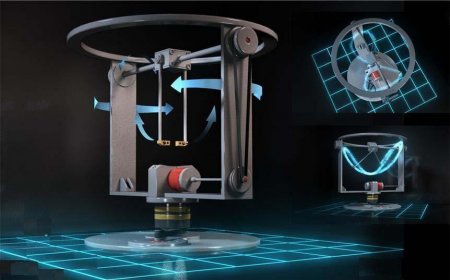
Figure 1. A prototype mechanism in its initial form.
Figure 2 is a clearer illustration of the testing antigravity mechanism in case of ω2 = 0 , with the two arms (rods) in the vertical position. This position corresponds to a rotation of 90 degrees with respect to the initial horizontal arrangement of the two rods. At this position, the centrifugal forces (exerted on the lumped masses attached to the free ends of the two rods) are directed downwards. Also, the ground plan of the figure-eight-shaped path is shown in the right.
Also, Fig. 3 shows again the figure-eight-shaped curved path in case of ω2 = 0 , with the arms (rods) in a skew position. This corresponds to a rotation less than about 30 degrees with respect to the initial horizontal arrangement. It can be noticed that the two rods are found on the same side with respect to the axis in the diameter of the outer thick horizontal ring of that picture.
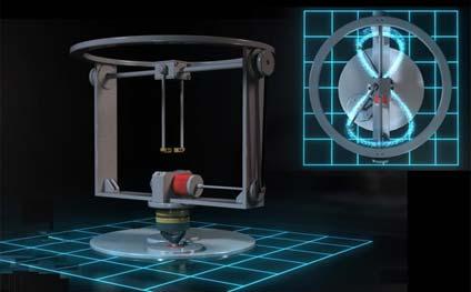
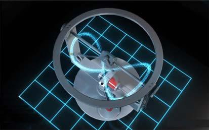
Figure 2. The rods are in the lower vertical position.
Figure 3. The figure-eight-shaped curve
with the rods in a skew position.In addition, Fig. 4 shows again the figure-eight-shaped curved path, with the arms (rods) in a skew position, but at different positions along the path. In this case the second rotation does not equal to zero but it is still small. Also, Fig. 5 illustrates the track the two masses cover when the second rotation is imposed as well, where for visibility purposes the path is eliminated at the right part.
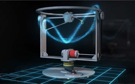
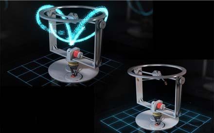
Figure 4. A different point of view where a small rotation around the vertical axis is imposed.
Figure 5. The track of the lumped masses when the second rotation is imposed.
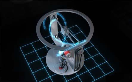
Figure 6. A ‘broken’ path due to spinning
around the vertical axisFigure 6 shows again the figure-eight-shaped curved path when the second rotation is also imposed ( ω2 ≠ 0 ); this time with the two arms being in already horizontal arrangement. It can be noticed that the ends of the arms are close to the upper points of the figure-eight-shaped curved path. It is also remarkable that the trajectory of the lumped masses is open, which means that after 360 degrees rotation the masses do not possess their initial position in the 3D space.
One of the possible practical ways to develop the abovementioned figure-eight-shaped curve has been previously described in Ref.28; the latter paper focused only on the description of the geometry of the mechanism and the mathematical equations of the figure-eight-shaped orbits using the angular velocity ω1 only. Furthermore, this paper extends the previous work and discusses, for the first time, the possibility of using this system as a propulsion/antigravity means. To this purpose, the key point is to spin the entire system using a second angular velocity ω2 .
III. Operation, elementary mechanics and experimental measurements
A. Application of the first rotation only: Description
In the particular case that only the first motor (rotation) operates while the second motor is off (ω2 = 0 ), a planetary system with four equal gears (two planets and two spin gears), can produce a trajectory with the shape of a figure-eight, i.e. the symbol of infinity (∞). In more details, every rod (of length r) is attached perpendicularly to the axis of the corresponding spin gear. The novel feature is that lumped masses, named ‘a’ and ‘b’, are attached to the free ends of these rods. For ideal conditions of rigid bodies, the aforementioned masses move along the surface of a sphere (particularly of a hemisphere) and their common trajectory, on which the two masses are mutually interchanged, preserves its orientation in the 3D space. In more details, let us assume that at the initial time (t = 0) the rod which corresponds to the first lumped mass ‘a’ (No. 153 in Fig. 7) is in the horizontal position; the latter position corresponds to the initial polar angle ø = 0 . At the same time, the second lumped mass ‘b’ (No. 154 in Fig.7) similarly corresponds to another horizontal rod.
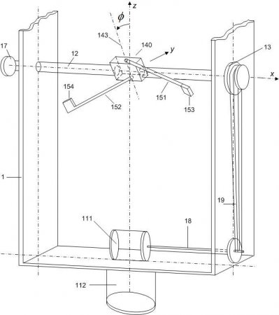
Figure 7. Implementation of the basic unit of the
antigravitation mechanism.Figure 7 presents an implementation of the basic unit of the antigravity mechanism. The mechanism consists of a frame (1) on which two (electric) motors are attached (111,112). The mechanism consists of a horizontal shaft (12) supported by the frame (1) and guided by the motor (111); in this implementation through the shaft (18) and belt (19) towards the end (13) of the shaft (12). The said shaft (12) includes in its interior other shafts that drive an attached planetic system (140) that is positioned preferably in the middle of the shaft (12). Two rigid arms/rods (151,152) are attached to the ends of the spin gears’ axis of revolution (143) where masses (153,154) are attached and regularly move on the path, without completing an entire circumference (they turn in complete harmony, without inertial problems, only by one hundred eighty degrees). During the rotation of the motor (111), the masses (153,154) move along a figure-eight-shaped path (not shown in this drawing), which entirely lies on the surface of a sphere the centre of which is the intersection of the horizontal axis (12) with the axis of the spin gears (143). Finally, the end of the shaft (12) includes a wheel (17), while the other end is driven by the motor (111); in this specific case through the belt (19). Also, a second motor (112) is illustrated at the bottom of the frame (1), which causes the rotation of the entire frame and consequently of the shaft (12) as well as of the attached masses (153,154).
Details concerning the attached planetic system (140) may be found elsewhere28,29
Although the full operation of this system gives the fake impression of a processing top (which could be generally be either rigid or elastic), from the above analysis it becomes evident that the proposed antigravity mechanism has no relationship with gyroscopic systems. Among many crucial differences, it is noted that the distance between the lumped masses ‘a’ and ‘b’ continuously varies in a great extent.
B. Application of the first rotation only: Elementary theoretical analysis
We study the particular case of two lumped masses, ‘a’ and ‘b’, which correspond to the masses 153 and 154, respectively, of Fig.7. Let us assume that at the moment of measuring the time (t = 0) the mass a (end of the arm 151) lies on an upper right horizontal position, while the mass b (end of the arm 152) lies on a lower left horizontal position. Neglecting the rotations involved (valid when more than one units operate), when only the first motor (111) operates (first rotation at an angular velocity ω1 ), both arms (151, 152) rotate by an angle φ = ωt ( ω generally differs than ω1), and then the position of the rotating masses are given as:28
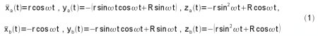
where r represents the common length (radius) of the arms (151,152) and R is the minimum distance between any of the said arms and the axis of symmetry of the shaft (12).
Based on the above equations (1), the corresponding components of the linear acceleration of these two masses
are described by the following relationships

Therefore, according to Second Newton’s Law, the centrifugal forces towards the vertical axis are given by:
Fza m z a t m 2 r cos 2t R cos t , 2(3) Fzb mzb t m 2 r cos 2 t R cos t 2
where m is each of the rotating masses. Therefore, the resultant vertical centrifugal force becomes: Fz Fza Fzb 4m 2 r cos 2p(4)
Apparently, equation (4) reveals a periodic variation, of amplitude 4mω²r , in the vertical resultant centrifugal force, a fact that advocates the incapability of the first rotation ( ω1 ) to achieve a permanent upward propulsion. Obviously, when the arms (151) and (152) lie on a horizontal position, then the position angle becomes zero ( φ = ω t = 0 ) and therefore the inertial forces become upward (of magnitude 4mω² r ). In contrast, when the arms (151) and (152) lie both on a vertical position ( φ = ω t = π / 2 ), then the inertial forces become downward (of magnitude 4mω² r ).
C. Both rotations
Obviously, when the second rotation of angular velocity ω2 is applied, then the profile of the inertial forces dramatically changes. Thus, a propulsive force the magnitude of which depends on the ratio ( ω2 / ω1 ), is produced.
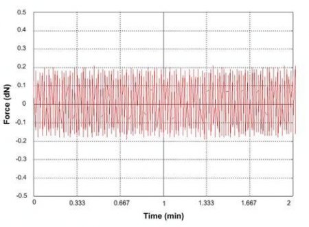
Figure 8. Weight variation versus time.
Using a commercial electronic scale equipped with proper software, a series of measurements have been performed to determine the variation of the vertical force component (i.e. the weight). A typical waveform for a combination of very low angular velocities is shown in Fig. 8, where an average difference of about 12% can be noticed for the positive and negative values. Although a theoretical explanation in the framework of either quasi-static30 or nonlinear dynamics (in the spirit of Ref. 31) might be possible, for the sake of briefness mathematical details will not be presented in this paper.
Instead, by simplifying the involved mechanics, here we limit the discussion in the fact that when the elastic rods are in the vertical position (like in Fig. 2) they suffer the minimal tension while when they are horizontal (like in Fig. 6) they obtain their highest elongation.
Therefore, the total impulse per period does not vanish, as happens in the trivial case of a circular path (i.e. in Dean space drive) in which the elastic rods always undertake the same elongation. In other words, while in case of a circular path (on a vertical plane) the upper and lower parts are equivalent (of opposite sign), the figure-eight-shaped path lies entirely above (or below) the center of the corresponding hemisphere and also the upper part is strengthened by the high centrifugal forces. Therefore, non-vanishing net impulse is produced.
IV. Discussion
Initial experiments on the prototype device are quite promising but not in all cases, particularly when the angular velocities are of low value. Another encouraging finding is that a quasi-static analysis of elastic bars in tension only, based however on the simplified assumption of constant angular velocities ω1 and ω2, has led to closed-form expressions which depict that the impulse directed along the axis of symmetry of the hemisphere includes a constant term plus three harmonics of the angle φ = ω t .30 Under the same simplified assumption of constant angular velocities, on-going theoretical research is currently conducted in terms of nonlinear dynamics and the finite element method.
It is remarkable that the direction of propulsion arises according to the position of the abovementioned hemisphere inside which the resultant curved path is created when the mechanism is in full operation. When the resultant curved path is formed in the lower hemisphere an upward force is produced, while when it is formed in the upper hemisphere a downward force is produced. Similarly, when the axis of symmetry of the hemisphere is horizontal or inclined (through the wheel (17) shown in Fig. 7), then propulsion is produced towards this axis and particularly towards the opposite direction.
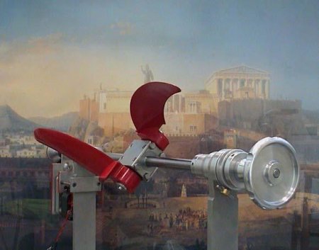
Figure 9. Prototype propeller based on a similar
principle with the antigravity mechanism.Of course, a more realistic simulation had to include the characteristic curves of the electric motors as was done by other researchers.32 However, such a consideration will probably lead to chaotic systems for which further research has to be conducted. In any case, we believe that this topic must be attacked by a combined high-tech experimental and theoretical investigation, in which high values of angular velocities should be tested. Although irrelevant to space applications, it has been already mentioned that the precursor of the proposed mechanism was firstly manufactured for water applications such as secondary propulsion for maneuvers to submarines; moreover, air applications such as RC ornithopters are also possible. With respect to Fig. 7, the main difference consists of replacing the rods (151) and (152) by wings as shown in Fig. 9, while the second motor (112) was omitted.
V. Design aspects
Although the abovementioned unit is capable of producing propulsive force along the vertical axis or any other desired direction, in this paper a still better design is also proposed, as follows:
- First, we increase the numbers of rods from two to four, so as forces and moments become balanced. The so obtained mechanisms are called basic units. In more details, when the lumped masses " a " and " b " ( No.153 and No.154 in Fig. 7) are found at the horizontal position, we also consider a pair of lumped masses " a' " and " b' " found at the vertical position. In this way, the phase difference between the pairs [ a , b ] and [ a' , b' ] equals to 90 degrees, thus leading to vanishing resultant inertial forces towards all three directions ( cf. Equations (2) and (3) ). However, it should be considered that the variable tensile elongation (due to inertial forces which highly depend on the polar angle φ ) leads to a higher value of the rod length, r, at the horizontal position ( e.g. for the pair [ a , b ] ) than the corresponding vertical position ( e.g. for the pair [ a' , b' ] ), thus leading to a net vertical inertial force Fz.
- Second, we use at least four basic units to built-up the so-called ‘stabilization and antigravity ’ system. When upward propulsion is desired, the aforementioned units could be arranged along a horizontal circumeference in equal distances. While the quasi-static analysis leads to continuously increasing thrust, it is hypothesized that an upper limit in the weight loss should be expected.
- Third, we use at least two units to compose the so-called ‘propulsion’ system. It should become clear that it is not absolutely necessary to use basic units to produce propulsion; other means such as small rockets, micro-jets, etc, may be also used.
VI. Conclusion
In conclusion, the proposed innovation is an integrated proposal for the achievement of an antigravity field as well as for propulsion. Every module within every basic unit composes a ‘gyroscope’-like element that draws only the upper (or lower) 180 degrees of the entire circumference (in other words, we have achieved to ‘brake’ the circular path thus creating a ‘half-gyroscope’), a fact that constitutes the most innovative issue of this basic research.
We believe that this idea will open new horizons in the field of Propulsion.
References
- 1 Oleson, S. R., and Sankovic, J. M., “Advanced Hall Electric Propulsion for Future In-Space Transportation,” NASA/TM-2001-210676.
- 2 Tajmar, M., Advanced Space Propulsion Systems, Springer, New York-Wien, 2002.
- 3 LaViolette. P. A., Secrets of Antigravity Propulsion: Tesla, UFOs, and Classified Aerospace Technology, Bear & Company, Rochester, Vermont, 2008.
- 4 Goebel. D. M., and Katz, I., Fundamentals of Electric Propulsion: Ion and Hall Thrusters, Wiley, New Jersey, 2008.
- 5 Crandall, R. P., They All Told The Truth: The Antigravity Papers, Trafford Publishing, Victoria, Canada, 2003.
- 6 Hauser, J., and Dröscher, W., “Gravitational Space Propulsion,” Proceedings of the 45th AIAA/ASME/SAE/ASEE Joint - Propulsion Conference & Exhibit, Colorado, 2009, Paper AIAA-2009-5069.
- 7 Dean, N. L., U.S. Patent for “System for converting rotary motion into unidirectional motion,” No. 2,886,976 (Filed 13 Jul.
1954; granted 19 May 1959).- 8 Cook, R. L., U.S. Patent for “Device for Conversion of Centrifugal Force to Linear Force and Motion,” No. 4,238,968, granted 16 Dec. 1980.
- 9 Chung, T. B., International Patent for “Internal propulsion apparatus of closed system using a Coriolis force,” WO 03/087574 A1, 23 (filed 08 April 2003; published 23 Oct. 2003).
- 10 Millis, M. G., and Thomas, N. E., “Responding to Mechanical Antigravity,” NASA/TM-2006-214390, AIAA-2006-4913, Dec. 2006.
- 11 Millis, M. G., “Assessing Potential Propulsion Breakthroughs.” In New Trends in Astrodynamics and Applications. ed. Edward Belbruno. New York: Annals of the New York Academy of Sciences, Vol. 1065, Dec. 2005, pp. 441–461.
- 12 Provatidis, C. G., “Some issues on inertia propulsion mechanisms using two contra-rotating masses,” Theory of Mechanisms and Machines, Vol. 8, No. 1, Apr. 2010, pp. 34-41.
- 13 Tanner, M. A., “Resonant Maglev Centrifugal Propulsion,” U.S. Patent Application US 2007/0079663 A1 (Filed: 12 Aug. 2006; Published: 12 Apr. 2007).
- 14 Robertson, D. B., WIPO Patent Application for “Propulsion method and apparatus utilizing centrifugal force,” World Intellectual Property Organization, International Publication Number WO 01/46584 A3, 28 June 2001.
- 15 Hoshino, M., U.S. Patent for “Propulsion apparatus using centrifugal force,” No. 20050139022 (Filed 7 Jan. 2004; Published: 30 June 2005).
- 16 Laithwaite, E., and Dawson, W., Gyron Ltd, U.S. Patent for “Propulsion System,” No. 5,860,317 (filed 5 May 1995; granted 19 Jan. 1999).
- 17 Hayasaka, H., and Takeuchi, S., “Anomalous weight reduction on a gyroscope’s right rotations around the vertical axis on the earth,” Physical Review Letters, Vol. 63, No. 25, 1989, pp. 2701-2704.
- 18 Hayasaka, H., Tanaka, H., Hashida, T., Chubachi, T., and Sugiyama, T., “Possibility for the existence of anti-gravity: evidence from a free-fall experiment using a spinning gyro,” Speculations in Science and Technology, Vol. 20, No. 2, 1997, pp. 173-181.
- 19 Quinn, T. J., and Picard, A., “The mass of spinning rotors: no dependence on speed or sense of rotation,” Nature, Vol. 343, 1990, pp. 732-735.
- 20 Wayte, R, “The phenomenon of weight-reduction of a spinning wheel,” Meccanica, Vol. 42, No. 4, Aug. 2007, pp. 359- 364.
- 21 Bergmann, P. G., Introduction to the theory of relativity, Dover, New York, 1976, Chap. 5.
- 22 Forward, R. L., “Guidelines to Antigravity,” American Journal of Physics, Vol. 31, No. 3, 1963, pp. 166-170.
- 23 Mashhoon B., Hehl, F. W., and Theiss, D. S., “On the gravitational effects of rotating masses: The Thirring-Lense papers,” General Relativity and Gravitation, Vol. 16, No. 8, 1984, pp. 711-750.
- 24 Møller, C., The Theory of Relativity, Oxford University Press, London, 1952, p. 717ff.
- 25 Tajmar, M., “Homopolar artificial gravity generator based on frame-dragging,” Acta Astronautica, Vol. 66, No. 9-10, May- June 2010, pp. 1297-1301.
- 26 Robertson, G. A., Murad, P. A., and Davis, E., “New frontiers in space propulsion sciences,” Energy Conversion & Management, Vol. 49, No. 3, March 2008, pp. 436-452.
- 27 Provatidis, C. G., “A critical presentation of Tsiriggakis’ gearless differential,” Mobility & Vehicles Mechanics, Vol. 29, No. 4, 2003, pp. 25-46.
- 28 Provatidis, C. G., “A novel mechanism to produce figure-eight-shaped closed curves in the three-dimensional space,” Proceedings 3rd International Conference on Experiments/Process/System Modeling/Simulation & Optimization (3rd IC-EpsMsO) [CR-ROM], edited by D. Tsahalis (Univ. Patras, LFME, Greece), July 2009 (also: print version in press).
- 29 Tsiriggakis, V. Th., and Provatidis C. G., U.S. Patent Application for an “Antigravity Mechanism,” No.61/110,307, filed 31 Oct. 2008.
- 30 Provatidis, C. G., “A device that can produce net impulse using rotating masses,” Dynamics & Structures Lab., Rept. MD&CS-888, National Technical University of Athens, Mechanical Engineering Dept., Athens, Greece, Dec. 2009; also: Engineering (http://www.scirp.org/journal/eng, in press).
- 31 Blekhman, I. I., Synchronization in Science and Technology, ASME Press, New York, 1988.
- 32 Kononenko, V. O., Vibrating Systems with a Limited Power Supply, Iliffe Books Ltd, London, 1969, p.24.
- Christopher G. Provatidis
